Raspberry Pi: driving a VU meter using a digital-to-analog converter
Posted on
As I've mentioned in previous blog articles, my wife and I have been working on driving an analog VU meter based on the sound going out the Raspberry Pi's audio outputs. This now works!
Here's a video demonstrating the result:
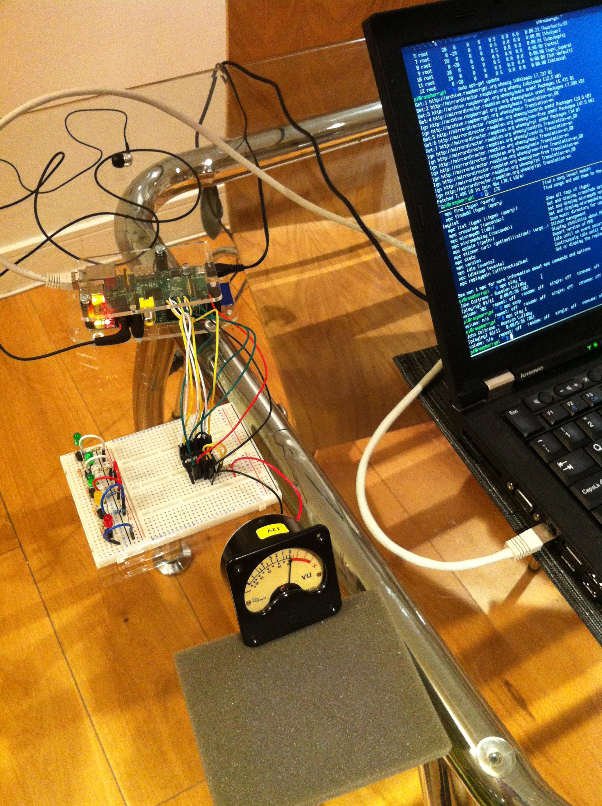
The music1 is playing from a Raspberry Pi, with software running on the Pi digitally sampling the peak output audio level and writing that out to an 8-bit digital-to-analog converter (DAC). The DAC output is then used to drive the analog meter. If you're interesting in knowing how all this hangs together, keep reading.
The Raspberry Pi is very capable of generating digital signals using its GPIO pins but an analog meter requires an analog signal. To convert a digital value emitted from the Raspberry Pi to an analog voltage we need a DAC. It's possible, and rewarding, to build a DAC using discrete components, but it's more convenient, accurate and reliable if you use an off-the-shelf DAC packaged as an integrated circuit (IC).
We've chosen to use the Analog Devices AD557. It has the following features:
- 8-bit parallel input: It takes 8-bit values as input (0-255) read via 8 individual (parallel) pins which are sampled at the same time.
- 5V single supply operation: The AD557 requires just a single 5V supply voltage. This is ideal for the Raspberry Pi where we have 5V power readily available. Many DAC ICs require a supply voltage somewhat higher than 5V making them trickier to use with the Pi.
- 0 to 2.55V output: A value of 0 at the input gives 0V at the output. A value of 255 at the input (the maximum) gives 2.55V at the output. This is easy to work with and think about.
- Flexible input voltage: The digital inputs accept values of 0 to 0.8V as "0", and 2 to 5V+ as "1", making them compatible with the 3.3V digital outputs on the Raspberry Pi.
- Low cost: Less concern about blowing it up!
Here's how the Raspberry Pi, DAC and VU meter were connected together:
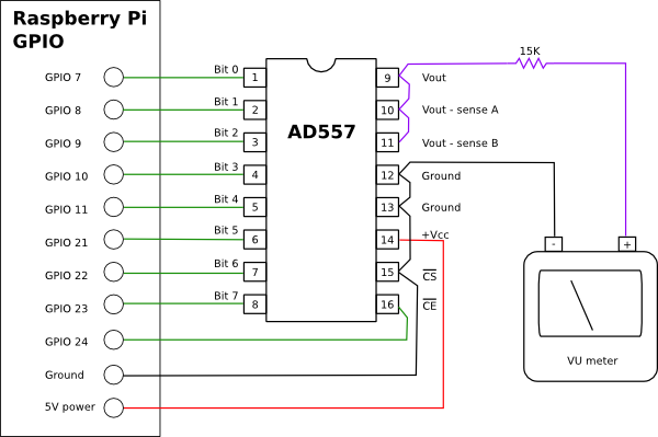
Various GPIO pins on the Raspberry Pi are used to provide a number between 0 and 255 to the data input pins (1 through 7) on the DAC. The power supply and ground for the DAC are provided by the 5V power and ground pins available on the Raspberry Pi GPIO header.
The slightly odd seeming output configuration involving three Vout pins is actually just what is required for normal operation. These three pins allow for alternate configurations where a non-standard output voltage range is required. See the AD577 documentation for more details.
The CS (chip select) and CE (chip enable) pins on the AD557 warrant some explanation. The DAC will only change its output voltage when both of these pins are low (at ground). This means that you can ensure you have the right values set on the data pins before telling the AD557 to update the output to the next value, ensuring unintended changes in output voltage are avoided while a new value is being set on the inputs.
There are use cases that require both the CS and CE pins to be used which I won't go in to here. Since we only need one of these pins here, CS is connected permanently to ground. CE is connected to a GPIO pin so we can control it from software running on the Raspberry Pi. The value on CE pin needs to be dropped from 1 to ground 0 for at least 225ns in order for the AD557 to update it's output voltage to a new value.
The 15K resistor is there to limit current. The Sifam audio level meter we're using is current driven, and needs very little current at that. It will show 0 (where the meter goes in to the red) at around 300uA. At the maximum output voltage from the DAC (5V), a 15K resistor will ensure the meter gets around 333uA (5 / 15000) which puts the needle nicely just in to the red zone.
Note that although this meter is marked as a VU meter, we are in no way indicating a true VU reading. The VU term has a strict definition which we're not trying to emulate in any real way here.
The code that drives this circuit is available on GitLab. The files are:
- dac.py: Some simple functions to initialise the GPIO ports and do writes of 8-bit values to the DAC pins.
- peak_monitor.py: Functionality to sample peak output audio levels using PulseAudio. See the previous article for more on how this works.
- vu_meter.py: Top level functionality which reads peak audio samples and writes them to the GPIO pins.
Have a look around. There really isn't that much code involved.
I hope you've found this post interesting and/or educational. My wife and I are about to solder up the circuit and get it and the Pi in to some kind of box. I'll certainly post some pictures of the result once that's done.
Irving Berlin's Russian Lullaby, performed by John Coltrane and band.